This is the first post on silencer modeling by using COMSOL MULTIPHYSICS. The goal is to present a tutorial series on how to modelling silencers under different conditions and the influence of the materials involved in the construction process of these acoustics devices.
All information presented here is product of the leisure and ... Bingo!! I don't have job. Is necessary more justification??.
Other important objective is write in English, If there are some mistakes, please let me know what, when and how to solve them. Is clear that the mathematics is more easy??
This and subsequent posts assumes some basic knowledge on acoustics, silencers, finite element method, COMSOL Multiphysics and common sense.
Here we go...
As the title says: I am going to present a brief tutorial on how to modelling a simple expansion chamber (without absortive material) by using Comsol v 3.2 package. In this post, an axial symetric 2D simple expansion chamber model is presented.
The parameters of the simple expansion chamber are:
r01=10 cm; L01=30 cm
r02=30 cm; L02=40 cm
r03=10 cm; L03=30 cm
1) Open Comsol Multiphysics and select Axial Symmetric 2D, Acoustics->Time Harmonic Analysis

2) Create the geometry

3) Set the constants (Alt+O+C)

where
rho_air: Air density
c_air: Sound velocity in the air
p0: Arbitrary pressure
4) Set the scalar expressions (Alt+O+E+c)

Where
Dt: Transmission Loss
Pin: Pressure at the input of the simple expansion chamber
Pout: Pressure at the output of the simple expansion chamber
5) Set Sub-domain settings (Alt+ y+ Enter)

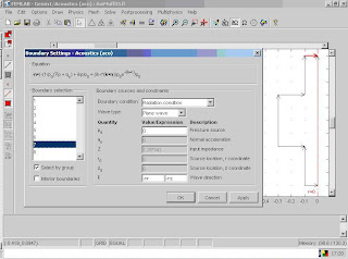
6) Set the boundary conditions (Alt+y+B)


7) Calculate the Intensity at the input of the simple expansion chamber (Alt +O+E+B)

8) Calculate the Intensity at the output of the simple expansion chamber (Alt +O+E+B)

9) Integrate the intensity on the input boundary in order to obtain Pin (Alt+O+r+B)

10) Integrate the intensity on the output boundary in order to obtain Pout (Alt+O+r+B)

11) Create and refine the mesh

12) Set the frequency on Scalar variables (Alt+y+V)

13) Set the solve parameters (Alt +S+ P)

The list of parameters values is arbitrary. In this case the frequency varies from 50 Hz to 2000 Hz in steps of 50 Hz. If you have a powerfull computer with enough RAM, you can calculate the transmission loss with more frequency resolution.
14) Press the “=” button
15) This figure presents the sound propagation at 500 Hz

16) Finally, the following steps are necessary in order to obtain the Transmission Loss
a) Go to the Postprocessing menu and select Domain Plot Parameters (Alt+P+D)
b) Select all frequencies from the Solutions to plot list in the Domain Plot Parameters dialog box.
c) Click the Keep current plot page.
d) Click the Title/Axis button and type Transmission loss in the Title edit field.
e) Click OK.
f) Select Point plot in Domain Plot Parameters dialog box and click on the Point tab.
g) Select point 1 from the Point selection list.
h) Type Dt in the Expression edit field.
i) Click the Line Settings button and select Triangle in the Line marker list.
j) Click OK.
k) Click Apply in the Domain Plot Parameters dialog box.


16) The Transmission Loss is:

Easy and funny, Your comments, suggestions and clicks on the publicity are welcomes (remember that I dont have job, help me pleeeease jajajja)
The next post will cover some Porous Material models
Yours sincerely,
Flaytech